Background
In 2022, testing of a redesigning weapons-carriage wing for the Leonardo AW159 Lynx Wildcat HMA2 helicopter has been concluded by the Royal Navy.
A specially equipped Wildcat HMA made 894 deck take-offs and landings over the course of 19 days and 87 hours of flight time. Seven weaponry configurations, including missiles under both weapon wings and one at a time, were successfully tested, and the Wildcat was put through its paces on a number of difficult approach and departure courses from the ship in day and night time. Defence Equipment and Support (DE&S) reported that “The Wildcat handled them all” [1].
The lightweight Martlet missile was fired from the helicopter during these operations in the Pacific Ocean towards an inflatable target in the water known as the “big red tomato.” The missile detached from the weapons wing, accelerating to one-and-a-half times the speed of sound towards the target, all in 0.3 seconds [2].
In recent years, Martlet made sure the Wildcat had the best-in-class offensive capacity to defend HMS Queen Elizabeth and her task group during her initial operational deployments. The Wildcats that were deployed with the task group served as a powerful deterrence to anybody intending to interfere with UK objectives, with each platform having the capacity to carry up to 20 Martlet [3].
Material
The new weapon wing’s “skin” is made of a brittle carbon fibre composite that is easy to chip, break, and delaminate. This might result in material degradation and significantly shorten the life of the tools being used. The interaction between the tool and the material during the machining process may be divided into three distinct contact areas, according to studies by Voss et al. [4].
- Micro-region 1: Zones that make initial mechanical contact with the composite material and are responsible for the separation of composites through the tool rake face.
- Micro-region 2: The tool tip radius zone and the zone that accounts for size effects in machining
- Micro-region 3: The zone that makes mechanical contact with the cut composite surface on the tool flank surface.
The primary cutting processes in micro-region 3 are characterised by intense friction between the tool and the carbon fibre and elastic recovery of the composite. As a result, drilling carbon fibre composites requires relatively complex cutting techniques, which poses a significant challenge for the commercial production of these materials.
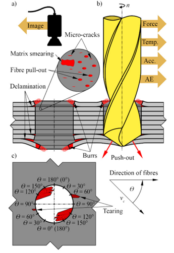
Drilling carbon fibre composites involves creating a number of major cutting-induced damages in addition to the difficulties related with the cutting processes, such as delamination, burrs, fragmentation, fibre pull-outs, micro-cracks, and matrix smearing [5–10].
These damages (shown in Fig. 1) should be taken very seriously when dealing with the drilling of carbon fibre since they seriously impair the surface quality and integrity of the cut composite material and are a major cause of component rejections throughout the assembly operations. The coupling effects of the chip removal mode, the cutting conditions, such as the cutting environments, the cutting speed, the feed rate, the tool-work system, etc., are strongly linked to the development of the aforementioned damages.
Drilling-induced delamination, which refers to the interlaminar de-bonding of plies of adjacent fibre layers and results in considerably lower bearing capacity, is commonly acknowledged as one of the most serious defects found within the cut composite surfaces. Peel-up delamination and push-out delamination are the two types that make up the delamination damage, which is a force-related failure [12–14].
Once the delamination damage reaches a certain point, the composite laminates must be rejected since it is irreversible. The disparities of the fibrous composites make it difficult to assess the extent of drilling-induced delamination.
Gandtrack Tools
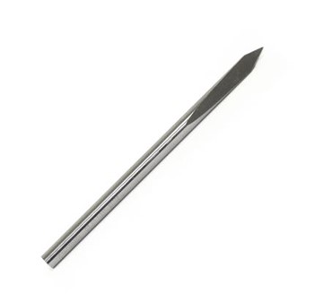
Solid Carbide Dagger Drill
GT 50 solid carbide dagger drill, with its unique drilling geometry, has continuously proved to be the best design of drill for drilling carbon fibre components because of its ability to reduce delamination whilst producing a quality sized hole.
The GT 50 is well suited for hand operations or CNC programs. The dagger drill with its special point makes it easy for drilling of carbon composite materials, due to the cutting forces being significantly reduced in the centre which reduced pushout. This is explained by the total cutting force (Fc) equation.
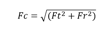
Where:
Ft = Tangential Force: The force responsible for shearing the material and is parallel to the cutting motion. This will be lower as the angle of the point gets sharper.
Fr = Radial Force: Responsible for pushing the drill into the workpiece and is perpendicular to the cutting motion. This will also be lower as the angle of the point gets sharper.
The efficiency of chip removal due to the special geometries of the dagger drill reduces the heat build up when cutting carbon fibre. Without this efficiency, the excessive heat can soften the resin matrix in composites, making them prone to delamination.
Materials
- CFRP -Carbon Composite Reinforced Polymers
- Carbon Fibre
- Glass Fibre
- Graphite Composites
Industries benefiting from using the GT 50 includes
- Aerospace – both manufacture and repair
- Marine – including world series racing teams and submarines
- Motor sport – including F1
- Model making
- Train components
- Military Pilot Helmet manufacture
Applications include:
- Drilling bushing
- Free hand drilling
- CNC controlled drilling
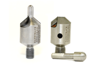
PCD Countersinks
When machining carbon composites, Gandtrack PCD Countersinks improve hole quality, allows accurate forming of holes and provides up to 10 times longer tool life. PCD is the only material that will successfully carbon fibre carbon fibre to such a high standard, while maintaining tool life.
Manufacturing Problems
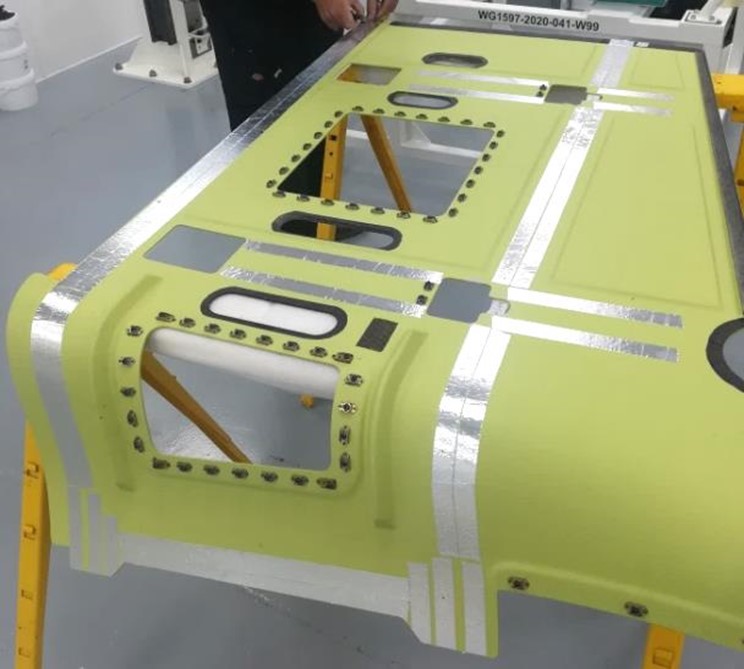
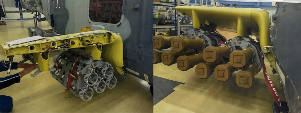
The Manufacturers of the weapons wing were experiencing delamination and damaged material and were failing to meet hole size tolerances. This was an issue that needed to be addressed immediately as there are 809 rivets on the wing alone.
As rivets are used, the holes needs to be countersunk. The PCD countersinks only have PCD tips on the cutting edge of the inclusive angle, as shown of the picture of the PCD countersinks, and the bodies are made from high speed steel. This meant that a pilot hole had to be drilled.
The weapons wing’s manufacturers were having problems with delamination and damaged materials, and they weren’t meeting specifications for hole size. The fact that there are 809 rivets on the wing alone made this a problem that needed to be resolved right away.
Countersunk holes are required when rivets are used. PCD is only used on the inclusive angle cutting face, and the bodies are constructed of high speed steel. As a result, a pilot hole needed to be drilled.
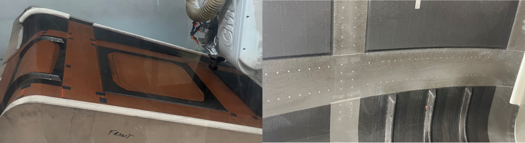
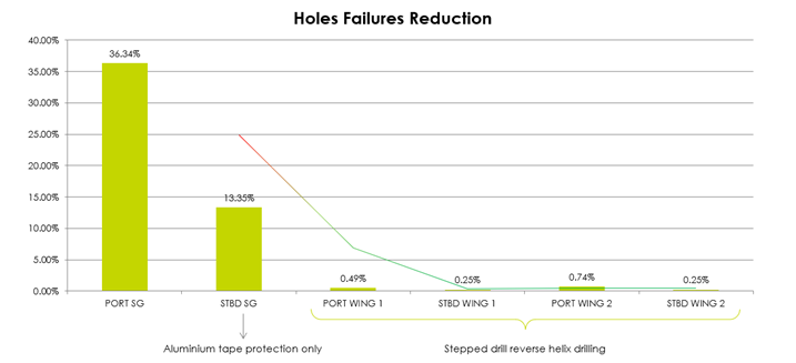
The initial solution was to try drilling using the same technique but protecting the inside surface with aluminium tape. The amount of swarf passing through the carbon holes was unchanged, but the tape provided a good level of protection for the inner surface of the skin (failures were decreased by 63%). Where the aluminium was thicker was where the vast majority of failures on the holes drilled using this procedure were discovered.
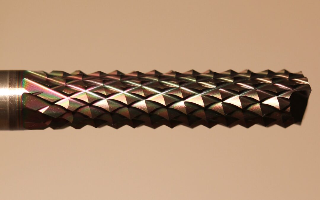
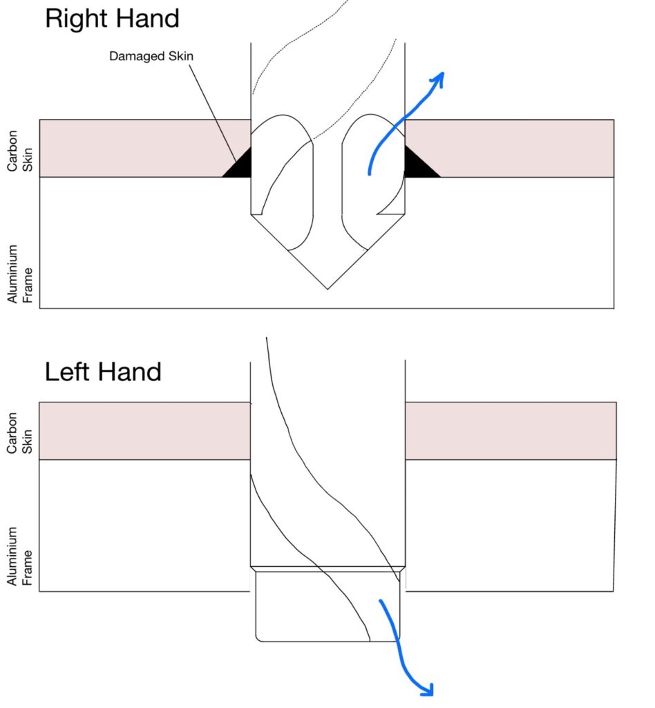
Left-hand helix drill
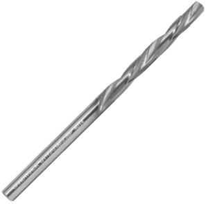
Due to the limited accessibility, right-hand drilling was not possible from the underside. The second approach was to use a Gandtrack left-hand helix drill with the flutes reversed and force the swarf through the hole from the top down. This meant that the carbon skin could not be damaged by the aluminium.
Using a left hand helix drill caused significantly fewer failures than using aluminium tape or using nothing at all, as shown in fig. To make the assembly of the weapon wings more efficient and successful, after working with the manufacturer of the weapon wings, they continue to employ Gandtrack solid carbide dagger drills, PCD countersinks, and left hand helix drills.
References
[1] (Jennings, 2022) https://www.janes.com/defence-news/news-detail/royal-navy-completes-wildcat-weapon-wing-trials
[2] (Royal Navy, 2021) https://www.royalnavy.mod.uk/news-and-latest-activity/news/2021/october/22/20211022-martlet-firing-carrier-strike-group
[3] (Sampson, 2020) https://www.aerospacetestinginternational.com/news/defense/leonardo-test-fires-thales-martlet-missile-on-widlcat-helicopter-for-first-time.html
[4] (Voss et al. 2019) https://www.sciencedirect.com/science/article/abs/pii/S0924013618303352
[5] (Gordon and Hillery, 2003) https://journals.sagepub.com/doi/abs/10.1177/146442070321700105
[6] (Kumaran, 2017) https://journals.sagepub.com/doi/abs/10.1177/0731684418819822
[7] (Liu et al., 2012) https://www.sciencedirect.com/science/article/abs/pii/S0263822311004387
[8] (Karatas and Gökkaya, 2018) A review on machinability of carbon fiber reinforced polymer (CFRP) and glass fiber reinforced polymer (GFRP) composite materials – ScienceDirect
[9] (Khashaba, 2012) https://journals.sagepub.com/doi/abs/10.1177/0021998312451609
[10] (Geier, N., Pereszlai, C., 2020).https://pp.bme.hu/me/article/view/14436
[11] (Geier et al., 2021) https://www.sciencedirect.com/science/article/pii/S2351978921001815
[12] (Geng et al. 2019) https://www.sciencedirect.com/science/article/abs/pii/S0263822318338406
[13] (Liu at al., 2012) https://www.sciencedirect.com/science/article/abs/pii/S0263822311004387
[14] (Hocheng and Tsao, 2005) https://www.sciencedirect.com/science/article/abs/pii/S0924013605006230
[15] (G. Fantinati, MEGGITT Aerospace, 2019)